Autonomy Modules
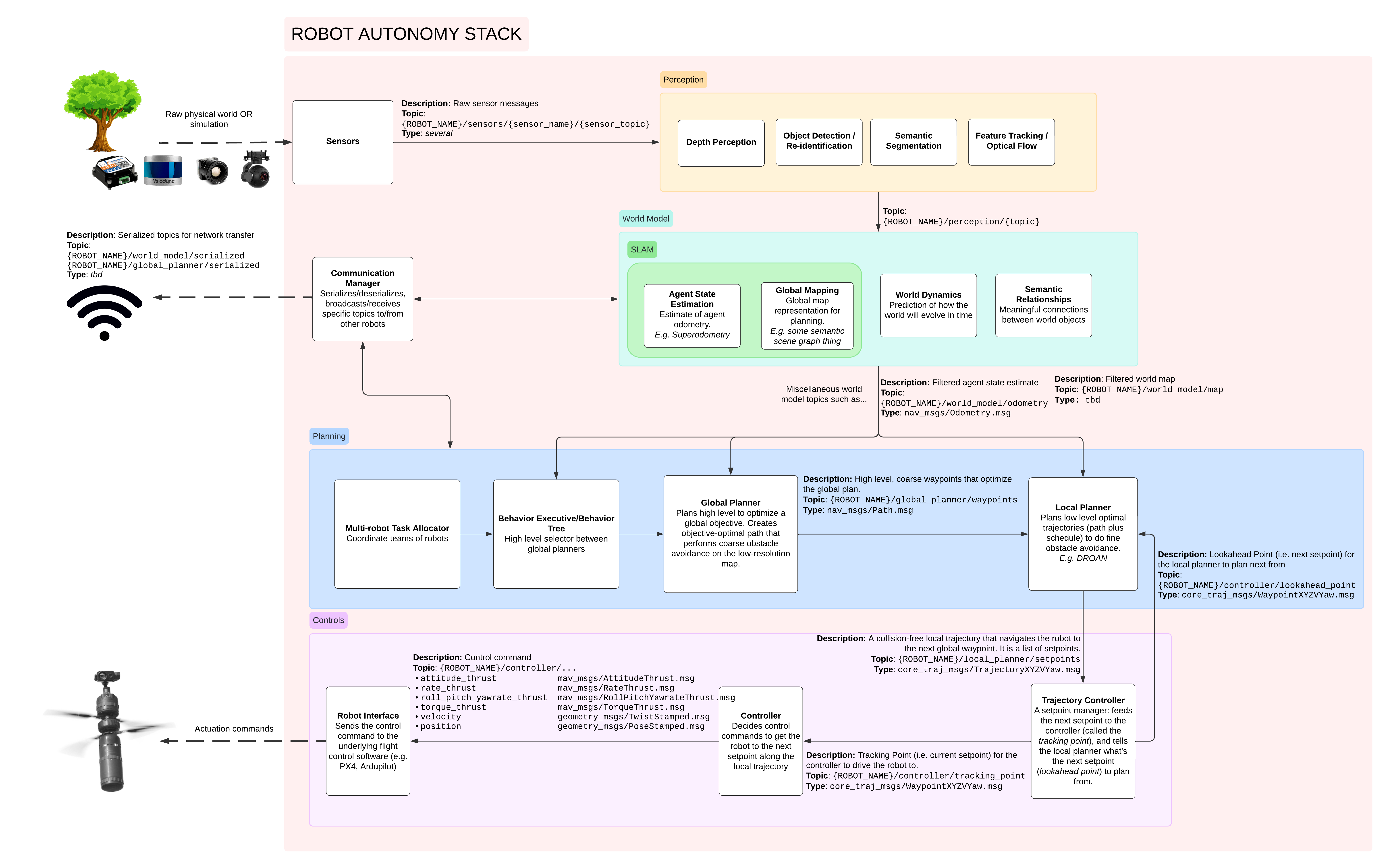
The onboard autonomy stack is organized into layers: data flows from sensors through perception and world models into planners, then down through controllers to the hardware interface. Each layer is a set of swappable ROS 2 packages that meet at the narrow interchange points defined in the Interface Conventions Specification, so an individual module (a planner, a controller, a mapper) can be replaced without rewiring its neighbors.
The Six Layers
- Interface — the bridge to the flight controller: command authority, arming, and MAVLink/MAVROS translation
- Sensors — driver/bridge topic normalization and robot-side preprocessing (e.g. LiDAR near-range filtering)
- Perception — state estimation: the odometry every downstream module consumes
- Local — short-range world model, reactive local planner, and the trajectory + PID controllers
- Global — persistent 3D mapping (VDB) and coarse global planning
- Behavior — the onboard safety executive
Alongside the layers, Coordination lets robots gossip state to each other and the GCS.
Perpetual Nodes vs Task Executors
Modules run in one of two styles. Perpetual nodes (state estimation, world models, controllers) run continuously from launch to shutdown. Task executors are action servers that only work when the operator sends a goal from the GCS — takeoff, land, navigate, explore — cascading from global-layer to local-layer executors. See System Architecture — Node Types and Task Executors.
Where Stacks Fit
Which modules run, and how they are wired, is decided by the selected stack: each layer's modules are composed by the stack's entry launch file (stacks/<name>/launch/*.launch.xml, e.g. stacks/full_default/launch/stack.launch.xml). See Stacks.
Key Resources
- System Architecture — architecture diagrams and data flow
- Interface Conventions Specification — the versioned contract at every module boundary
- Integration Checklist — guide for adding new modules
System Diagram