2D World Map in Foxglove
There are two ways to render a 2D ground reference under your fleet in Foxglove's 3D panel:
- Real-world satellite images — for outdoor flights. Foxglove's built-in Map panel fetches satellite/road tiles from an online tile provider and pins your robots on them via GPS.
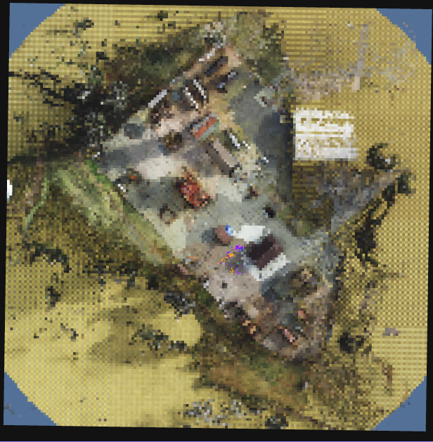
- Simulated overhead camera — for sim. A static top-down orthographic camera captures the scene once and publishes it as an aerial image; the GCS renders it as a textured ground plane.
Both paths render into the same global map frame, so robot markers, trajectories, and gossip payloads sit correctly on top in either case.
Real-World Satellite Images
For outdoor flights, no special AirStack configuration is needed — the GCS publishes everything Foxglove's Map panel needs:
- Each robot's GPS gets republished on
/gcs/{robot_name}/location(withframe_id='map'so the Map panel accepts it). - A stationary fix at
ORIGIN_LAT/LONis published on/gcs/map_origin/locationso the panel has a fixed anchor and doesn't auto-recenter on whichever robot moves first.
In Foxglove:
- Add a Map panel.
- Open its settings and pick a tile layer (e.g. Custom (URL template) with a satellite tile provider — Foxglove ships with OpenStreetMap by default; for satellite imagery you can use any standard
{z}/{x}/{y}URL such as Esri's World Imagery). - Add
/gcs/map_origin/locationand each/gcs/{robot}/locationtopic.
The Map panel will draw satellite tiles around the origin and show robot pins as they move.
Simulated Overhead Camera
The overhead camera is a static, top-down orthographic camera that renders the simulated scene once and publishes it as an aerial image. The GCS picks it up and renders it as a textured ground plane in Foxglove's 3D panel — useful as a visual reference behind the robot markers, especially in scenes that don't have ground-truth satellite imagery.
The scene is static, so the camera publishes briefly at startup, the GCS catches one valid frame, and both sides tear down their subscriptions. After that, the overhead is essentially free.
Enabling it in a sim launch script
Two helpers from simulation/isaac-sim/utils/scene_prep.py do all the work. Call both inside the post-load callback (after the stage is loaded but before drones spawn):
from utils.scene_prep import (
    add_orthographic_camera, add_overhead_camera_publisher,
    get_stage_meters_per_unit,
)

mpu, scene_scale_factor = get_stage_meters_per_unit(stage)

cam_path = add_orthographic_camera(
    stage,
    prim_path="/World/MapCamera",
    altitude_m=OVERHEAD_ALTITUDE_M,
    coverage_m=OVERHEAD_COVERAGE_M,
    scene_scale_factor=scene_scale_factor,
)

add_overhead_camera_publisher(
    parent_graph_path="/World/MapCameraGraph",
    camera_prim_path=cam_path,
    topic="/sim/overhead/image",
    spec_topic="/sim/overhead/spec",
    frame_id="map",
    coverage_m=OVERHEAD_COVERAGE_M,
    pixels_per_meter=OVERHEAD_PX_PER_METER,
    domain_id=0,
)
The three constants (OVERHEAD_ALTITUDE_M, OVERHEAD_COVERAGE_M, OVERHEAD_PX_PER_METER) are the only knobs you typically need to adjust. Defaults and effect:
| Constant | Default | What it controls |
|---|---|---|
OVERHEAD_ALTITUDE_M |
150.0 |
Camera height above world origin (m). |
OVERHEAD_COVERAGE_M |
200.0 |
Side length of the captured square (m). |
OVERHEAD_PX_PER_METER |
4.0 |
Texture density. Increase for sharper text/markings; capped at max_resolution=2048. |
Re-centering or transforming the camera
By default the camera sits over world origin (0, 0). For an off-origin area of interest, pass center_x_m / center_y_m to both helpers — they take care of the camera xform and the spec topics the GCS reads:
CENTER_X_M, CENTER_Y_M = 50.0, -25.0

cam_path = add_orthographic_camera(
    stage, prim_path="/World/MapCamera",
    altitude_m=OVERHEAD_ALTITUDE_M,
    coverage_m=OVERHEAD_COVERAGE_M,
    scene_scale_factor=scene_scale_factor,
    center_x_m=CENTER_X_M,
    center_y_m=CENTER_Y_M,
)

add_overhead_camera_publisher(
    parent_graph_path="/World/MapCameraGraph",
    camera_prim_path=cam_path,
    topic="/sim/overhead/image",
    spec_topic="/sim/overhead/spec",
    center_x_topic="/sim/overhead/center_x",
    center_y_topic="/sim/overhead/center_y",
    frame_id="map",
    coverage_m=OVERHEAD_COVERAGE_M,
    center_x_m=CENTER_X_M,
    center_y_m=CENTER_Y_M,
    pixels_per_meter=OVERHEAD_PX_PER_METER,
    domain_id=0,
)
GCS side
The GCS rendering is handled by _build_sim_ground_marker in gcs/ros_ws/src/gcs_visualizer/gcs_visualizer/foxglove_visualizer_node.py. It:
- Downsamples the source image to a coarse triangle grid (default 0.8 cells/m, capped at 384×384) — Foxglove's 3D panel struggles with dense per-pixel meshes, but a coarse triangle grid renders smoothly.
- Publishes one
Markerof typeTRIANGLE_LISTon/gcs/sim_ground.
Hide the overhead in Foxglove
The ground plane is just a marker on /gcs/sim_ground, so you can toggle it on or off in the 3D panel settings without touching any code:
- Click the gear icon on the 3D panel.
- Open Topics →
/gcs/sim_ground. - Toggle visibility off to hide it.
Sharper rendering
The default downsample (0.8 cells/m, cap 384) is conservative. To raise the rendered resolution, override two parameters on foxglove_visualizer_node in gcs/ros_ws/src/gcs_visualizer/launch/gcs_visualizer.launch.xml:
<param name="overhead_grid_per_m"           value="3.0" />
<param name="overhead_max_grid_resolution"  value="1024" />
To change other rendering behavior (alpha, lighting), edit _build_sim_ground_marker directly. To force a re-render, restart the GCS visualizer.
See also
- Spawning Drones — authoring a full multi-drone launch script
- Pegasus Scene Setup — single-drone scene authoring
- GCS Foxglove Visualization — what the visualizer publishes alongside the ground marker